 Recommend to StumbleUpon
This is a first pass at presenting some basics. Most of my pages are more polished!
I will be addressing multimeters "in general"... you will have to consider how what follows applies to your multimeter.
In The Bad Old Days, to measure voltage, current or resistance took three different instruments. And they were fragile. And, unless you paid a lot, not very accurate. AND they distorted what was going on in the circuit, when you used them. Maybe Heisenberg was an electrical engineer! (His principle actually talks about something more esoteric... but there are parallels.)
Happily, we live in more blessed times. We can obtain, for very little, one box which will measure all three... and often other things... well.
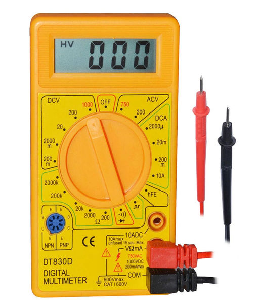
Nothing's for nothing, though! First there's the fact that while almost always, measurements are made with just two connections between meter and circuit, usually the multimeter will have three places for plugging in the "leads". (Usual name for wires between meter and circuit.) (My thanks to https://probots.co.in/ for the image... it is something they were selling, in India. (The blue circular "thing" at the lower left is a place to plug in transistors for testing... how to do those tests is not going to be part of this.))
And there's the big dial in the center.
Decide what you are going to measure. Voltage? Okay. AC or DC? Turn the dial to one of the places appropriate to measuring that.
Don't, for now, worry about why one lead is red, the other black.
One of the holes may well be labeled "Com", for "common"... as in "this hole is shared, in common, between all the measuring modes." Or other markings may help you. Or, RTFM!
Usually, people put the black lead in the "COM" socket. (But you CAN put the red one there, without causing damage.)
The OTHER cable goes in... ta da!... one of the OTHER holes!
Which one will be determined by what you are wanting to measure. Again, markings on the face of the multimeter, etc, will guide you.
IT DOES MATTER!.... Getting the other lead in the wrong hole can be a problem, if you connect the leads up to a circuit with a bad combination of hookup/ dial position/ holes used. (But it won't OFTEN be a problem... beyond you not getting the measurement you were hoping for.
One little bit of "good news", to "cut down" the choices: I can't think of a case where you would not use the hole we talked about first. Assuming of course that the hole you guessed was your "com" connection is your "com" connection, that will be a help. (You'd never put the leads in both of the other holes for any measurement.)
Now we look at the details of measuring voltage, or current, or resistance.
But first: Please "do not try this at home": Please do not try using your multimeter on anything other than low voltage circuits (less than 25 volts) and things powered by sources that can't generate much current. You will, probably, use one on a circuit powered by a Lipo battery. Low voltage. Good. But those batteries can supply very dangerous currents. In a perfect world: Don't work with lipos if you are a novice. Or at lease, please, try to avoid, for now? Work on something else, gain some experience and knowledge. If you are a bit beyond novice, or just ignoring my please: Treat anything with a Lipo with extra respect.
So... measuring...
This is the easiest! You DO need to notice if you are working with AC or DC, and set the dial accordingly. (If you try to measure an AC voltage with the dial set for DC, you'll get a reading of about zero.)
Other than that, you just carefully connect the leads to the two points, and the voltage reading should appear.
Using a meter isn't all about fancy stuff. Don't forget the simple.
"The simple": When you connect the leads to the circuit, be careful that the lead only touches things it is meant to. Suppose you are using simple leads with just a metal spike which you press against the bit of the circuit you want a voltage from. Don't let that metal spike create a short circuit between what you wanted it touching, and something close by that!
Before you can use a voltmeter with true understanding, you need to learn that when some says "the voltage here is 5v", they are using a shorthand. "The voltage" is never measured at one point. That's why you need to use two leads to measure it! Voltage is something that only makes sense when you talk about TWO places.
If I say Mount Everest is 29,000 ft (and a bit) "high", you know that I mean that it is 29,000 ft above sea level. (When you stand in the valley below it, you don't have 29,000 ft to go to get to the top.
So... in "heights" of hills, etc, we are talking about the difference between sea level and the top of the hill.
In electronics, when someone says "it" is 5v, they mean that the voltage between "it" and some other place is 5v.
If the "other place" isn't specified... as it usually isn't... then the other place is the circuit's ground, or "zero volts". The "negative" end of a battery is the ZERO, not negative, volts point in a battery driven circuit.
There ARE times when you want to know the voltage between two points, neither of which is ground, and you measure them the same way... but why you would is a story for another day.
A bit of good news, though you may not see why at the moment: When the dial is set for measuring voltage (AC or DC), there is almost no path for electricity though the multimeter. (A very, very small amount will flow... but it won't be a problem to meter or the circuit "under test". (The one you are making measurements on.)
If you set the dial to measure current, you need to be very, very careful. (In the case of some meters, you will also need to move the cable that isn't in "com" to the other of the "other holes"... if you see what I mean!.)
When you connect the meter with it set to measure a current, then there will be a path between the leads, inside the meter, with almost no resistance at all.
This can be very very bad.
If, for instance, you set up the meter to read current, and connect one of the leads to the "positive" end of a battery, and the other to the "negative" ("zero" would be a better name) end of the battery, then a lot of current will flow through the meter, and through the battery.
There may be a fuse inside the meter. It may "blow", and then need replacing. There may be no fuse, and the meter would henceforth not measure current. (And I'd be worried about the accuracy of other readings.) The battery will be "run down" quite quickly, if you leave everything connected, and the high current flowing.
The less bad bit of news about measuring current, is that making the connections for that is slightly troublesome. Well, troublesome compared to the NO TROUBLE "making connections" required for voltage measurements.
I'll give you the details in a moment.
Remember a moment ago I talked about voltage always being between two points?
With current, you are always talking about "the current at one point.
To measure that current in a working circuit, you need to "break" the circuit at that point, and then "bridge" the gap with your multimeter.
Any place you would sensibly do that, the current there is already limited to reasonable levels by other elements of the circuit. As your meter presents virtually no resistance to the current, the circuit won't "know" that it is there!
And lastly, resistance.
Resistance is like voltage. It is always a measurement "across" two points.
Measuring resistance is a bit unlike measuring voltage, because the meter will put a small current through whatever is being measured.
I generally only measure the resistance of passive components. (I.e. not ICs, transistors.)
I generally measure things in isolation, "outside" of any bigger circuit. (In a circuit, there are usually paths for the current from the meter to flow that you haven't thought of!)
I often test the resistance between various parts of a printed circuit before I install any components, and sometimes during the assembly. (If there is low resistance between the ground track and the Vcc track before you've put in any components, then something is wrong!!)
When testing, say, a resistor, be careful not to be holing BOTH leads to a pin with your thumb and finger. One is fine, but if you do both, some of the current that the meter sees flow will be flowing through you! (And the reading will be falsely low.)
When testing the resistance of diodes, you have to test "both ways 'round"... the current from the meter flows a certain way, and diodes only pass current one way.
When testing the resistance of a capacitor... an unlikely thing to want to do, but still, "learn this": It will seem to have "no" resistance briefly, and then gradually the resistance will rise. (Sometimes "gradually" will be the blink of an eye... other times it will be hours.) Eventually the resistance should be in the meg-ohms. Or many meg-ohms. If it is an electrolytic, or other polarized capacitor then again, as with the diode, the behavior under test will be different depending on how you connect the leads. (Probably not a good idea to do a prolonged test with them "backwards".)
Many multimeters will do more than "just" measure The Big Three. (Voltage, current, resistance.)
A common "extra" is a continuity tester... basically a simple resistance meter that beeps when the leads are touched together, directly, or indirectly through something that has no resistance.
The comments I made about measuring resistance apply to this mode, too.
In addition, be aware that sometimes there is a brief delay before the beep starts. Do not "wipe" the test lead across contacts, if looking for short circuits on an unpopulated PCB. Press the moving lead quite deliberately onto each place that is of interest, and hesitate just a moment... 200ms?... before moving on to the next path you want to check.
What newbie gotchas have I missed in the above? What in it could be misunderstood by a novice?
Search across all my sites with the Google search button at the top of the page the link will take you to.
Or...
Search just this site without using forms,
Or... again to search just this site, use...
The search engine merely looks for the words you type, so....
*! Spell them properly !*
Don't bother with "How do I get rich?" That will merely return pages with "how", "do", "I", "get" and "rich".
I have other sites. My Google custom search button will include things from them....
One of my SheepdogGuides pages.
My site at Arunet.
This page's editor, Tom Boyd, will be pleased if you get in touch by email.
![]() Page tested for compliance with INDUSTRY (not MS-only) standards, using the free, publicly accessible validator at validator.w3.org. Mostly passes. There were two "unknown attributes" in Google+ button code, two further "wrong" things in the Google Translate code. Sigh.
Page tested for compliance with INDUSTRY (not MS-only) standards, using the free, publicly accessible validator at validator.w3.org. Mostly passes. There were two "unknown attributes" in Google+ button code, two further "wrong" things in the Google Translate code. Sigh.